Tree View
Tree View is a temporary page located on the Model Window
for making and view drawings of DEXi Models tree structure.
This page can be created by View/Tree graphic... command while located on the
Model Page. At most one Tree View page is allowed. On this page, you can:
Interactively design a drawing of tree structure by
choosing between four tree-drawing algorithms,
selecting the drawing direction, and
modifying an extensive set of drawing parameters.
Save the drawing to a file, or copy the drawing to clipboard for transferring to other applications. Two graphic formats are supported:
Windows Enhanced Metafile (
.emf): a vector graphic format,Bitmap (
.png): a bitmap graphic format.
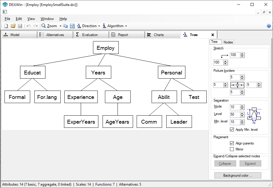
Workspace
The workspace consists of a drawing display on the left and control area on the right. The latter consists of two tabs for controlling the display of Tree elements and individual Nodes. The latter contains two additional tabs, Graphic and Text.
It is possible to choose one or more tree nodes on the drawing:
Mouse click: Selects the clicked node and deselects all others.
Ctrl + Click: Selects or deselects the clicked node.
Selected nodes are indicated by a blue rectangle, drawn around them.
Commands
Tree View commands are available from the File, Edit and View menus, on the toolbar and from the pop-up menu that appears after right-clicking the mouse in the drawing area.
File/Save tree…: The current drawing can be saved on a file using one of the mentioned formats: metafile or bitmap.
 Edit/Copy as metafile…: Copy the current drawing to the clipboard using the metafile format.
 Edit/Copy as bitmap…: Copy the current graphic to the clipboard using the bitmap format.
 View/Zoom…: Adjusts the zoom level of the drawing. In addition to some predefined
zoom percentages (from 5% to 500%), standard zoom levels can be selected:
 Actual size
 Show full drawing on the page
 Expand the drawing to cover full page width
Direction: Tree View can draw trees in four different directions:
 Top-Down,
 Left-Right,
 Bottom-Up, and
 Right-Left.
The Top-Down direction places the root of the tree at the top of the drawing and branches the tree downwards. The other three directions in turn correspond to 90-degree counter-clockwise rotations of the tree structure. Displayed text is never rotated.
Algorithm: Tree View uses four different node-positioning algorithms:
 Distribute: For Top-Down and Bottom-Up drawings, this algorithm horizontally
distributes leaves of the tree so that each leaf occupies its own
vertical range. This algorithm works especially well for Left-Right and
Right-Left drawings, where each leaf occupies one “line” of the drawing.
 Align: The same as Distribute, except that all leaves are aligned at the same
(lowest) level of the drawing.
 Walker: This is an implementation of the Walker’s algorithm, which is
particularly suitable for Top-Down and Bottom-Up drawings. In principle,
this algorithm tries to move sub-trees together as close as possible
while maintaining some tree-drawing “aesthetic criteria”.
 QP: This is our own version of a “stress-minimization” algorithm that
positions tree nodes by solving a constrained quadratic minimization
problem. Typically, this algorithm uses the available drawing space very efficiently
and makes pleasant drawings, while possibly violating some “aesthetic criteria”.
Tree View Settings
The tabs shown on the right side of Tree View contain numerous controls to affect the appearance of the tree and its components. Notice that the Node page has two sub-pages: Graphic and Text.
Tree Page
The Tree Page parameters affect the placement of the tree as a whole.
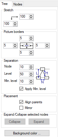
Stretch: Percentage of additional horizontal and vertical stretching of the drawing.
Picture borders: Additional pixels added at each side of the drawing.
Separation: [all units are in pixels]
Node: Separation of two adjacent nodes. More precisely: horizontal separation for Top-Down and Bottom-Up drawings, and vertical separation for Left-Right and Right-Left drawings.
Level: Separation of two adjacent levels.
Min. level: Minimum distance between two node boxes that appear at adjacent levels. This applies when node boxes become too large (e.g., due to displayed text) to fit between the Levels.
Apply Min. level: Check to activate the Min. level.
Placement:
Align parents: When checked, each parent is placed centrally above all of its descendants in the tree. Otherwise, it is centered only above its immediate descendants (“children”). Align parents does not work with the “QP” algorithm.
Mirror: Mirrors the whole tree. This is especially useful for Left-Right drawings so that the leaves appear in the “logical” top-down order.
Background color: This button activates a dialog for selecting the background color of the whole drawing.
Expand/collapse selected nodes: Two buttons, Collapse and Expand are enabled when one or more nodes are selected in the drawing. Pressing the buttons collapses or expands the selected subtrees, respectively. In this way, you can trim off some subtrees and show just a portion of the whole tree.
Node Page
The Node Page controls the display of tree nodes. It has two sub-pages: Graphic and Text.
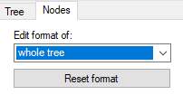
At the top of the Node Page, you can select the class of nodes or a specific node to which tree-drawing controls, displayed on sub-pages below, apply. The available node classes are:
selected nodes(s)
whole tree
aggregate attributes
basic attributes
discrete inputs: basic attributes associated with qualitative scales
continuous inputs: basic attributes associated with continuous scales
linked attributes
root attributes
collapsed nodes
Reset format: This button resets the format of the selected category of nodes to default values.
Node/Graphic Page
This sub-page defines graphical properties for displaying the selected category of tree nodes.
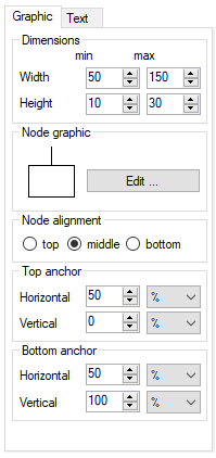
Dimensions: Sets the minimum and maximum dimensions of the node “box” [in pixels]. When the minimum and maximum are different, the actual “box” dimensions are determined according to the text displayed in the box.
Node graphics: Opens a dialogue for configuring the graphic display of nodes. The dialogue settings include:
Line: Setting the style, width and color of node-connecting lines.
Shape: Shape type for displaying the node: Rectangle, Ellipse, or Rounded. For Rounded, the radius of edges [in pixels] can be defined, too.
Border line: Setting the style, width and color of node border lines.
Fill: Setting the style, color and hatch pattern of node interior.
Node alignment: Refers to how are node “boxes” of different dimensions positioned at one tree level, that is, whether they are aligned at their top, middle or bottom positions.
Top anchor: Defines the originating point position for the line that connects nodes with their parents. These points are defined relative to the node “box” and can be expressed in terms of pixels or percentages.
Bottom anchor: Similar to “Top anchor”, except that it refers to lines that connect nodes with their descendants in the tree.
Node/Text Page
This sub-page defines properties of text displayed in the selected category of tree nodes.
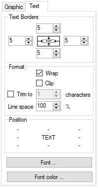
Text borders: These controls define internal borders [in pixels] that separate displayed text from the surrounding node rectangle.
Format:
Wrap: When checked, the text can be wrapped so as to fit in the node “box”.
Clip: When checked, only the text within the “box” is displayed. Any text or its part that does not fit into the box is not displayed.
Trim to: Here you can specify the maximum number of displayed characters. This is useful for trimming long node texts.
Line space: For wrapped text, specify line spacing. 100% refers to single spacing.
Position: Provides nine clickable elements for specifying text position in the node “box”. Horizontally, the displayed text can be left-justified, centered or right-justified. Vertically, the text can top-aligned, centered or bottom-aligned.
Font ..: Choose font for displaying text in nodes.
Font color …: Choose font color for displaying text in nodes.
Examples of Tree Views
This example illustrates the main Tree View drawing types, displaying the structure of Car Evaluation model.
Top-Down Orientation
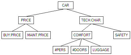
Algorithm: Distribute
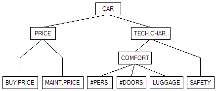
Algorithm: Align
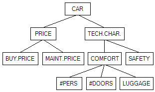
Algorithm: Walker
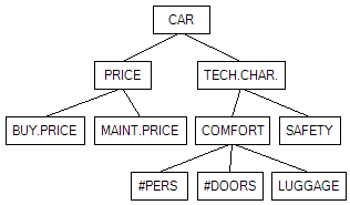
Algorithm: QP
Left-Right Orientation
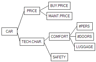
Algorithm: Distribute
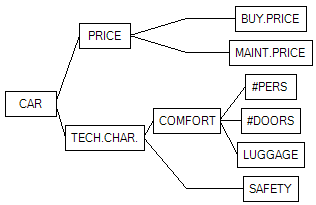
Algorithm: Align
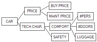
Algorithm: Walker
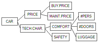
Algorithm: QP